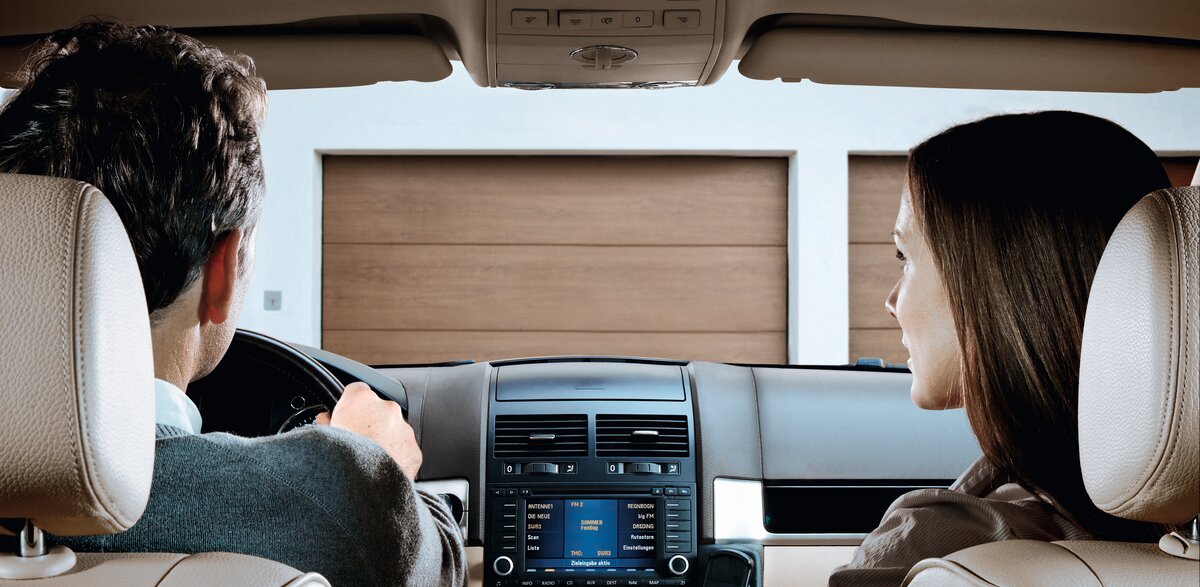
More comfort & safety through our radio system
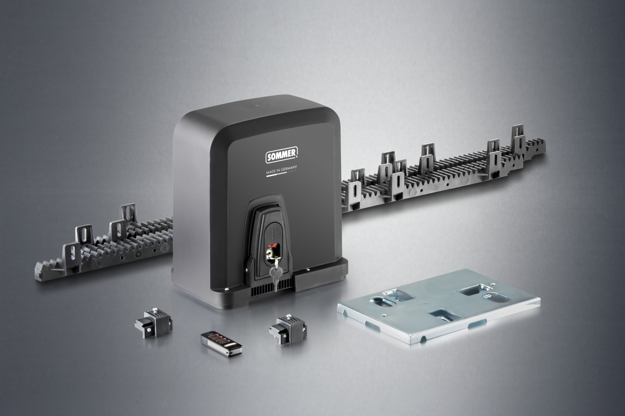
Sliding Gate Operators STArter S3/S3+

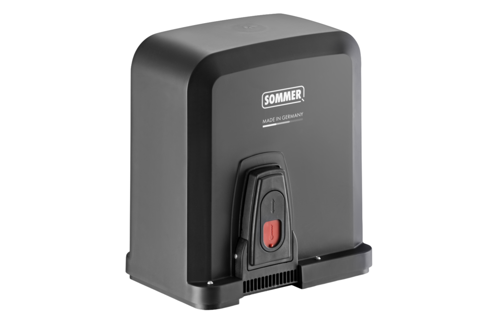
STArter S3 / Starter S3+
Smart sliding gate operators with impressive travel dynamics
The STArter S3 / STArter S3+ from SOMMER is a smart sliding gate operator for small to medium-sized gates.
It is ideally suited for gate weights up to 300 kg and travel distances up to 6 m (S3) or up to 400 kg and 8 m (S3+).
It is ideally suited for gate weights up to 300 kg and travel distances up to 6 m (S3) or up to 400 kg and 8 m (S3+).
Technical data
The use of active safety contact edges on the main and secondary closing edges is mandatory for the STArter S3+.
| STArter S3 | STArter S3+ | |
|---|---|---|
| Gate weight max. | 300 kg | 400 kg |
| Max. travel path | 6,000 mm | 8,000 mm |
| Max. opening speed | 190 mm/s | 410 mm/s |
| Max. torque | 12 Nm | 13 Nm |
| Power consumption (standby) | 0.5 W | 0.5 W |
| Rated voltage range 1 | 100-240 V | 100-240 V |
| Rated frequency | 50-60 Hz | 50-60 Hz |
| Temperature min. | -20 °C | -20 °C |
| Temperature max. | 50 °C | 50 °C |
| Protection class | IP54 | IP54 |
| Radio system | SOMloq2 | SOMloq2 |
| Radio frequency | 868.95 MHz | 868.95 MHz |
| Radio memory locations | 40 | 40 |
Product advantages
- no active safety contact edge required on the main closing edge* (does not apply to STArter S3+)
- maintenance-free operator with long service life
- high safety thanks to fully automatic force learning
- 24 V technology with controlled soft run
- automatic closing and partial opening adjustable
- Motor control unit STA STArter S3 ST-C-1: integrated in the housing
- convenient and error-proof connection thanks to pluggable, color-coded terminals
- all inputs and outputs are equipped with status LEDs
- compatible with the SOMweb smart home solution
- serial interface for the Delta Dore X3D module or HomeLink radio receiver module
- bidirectional, secure radio system SOMloq2 thanks to 128-bit AES encryption
- wide range of accessories for expansion (e.g. memory expansion Memo, additional relay Relay, open-collector output Output OC)
- numerous setting and query options via SOMlink
- manual release: With SOMMER sliding gate operators, the gate can be easily locked and unlocked in any position.
- rack: Plastic rack with steel core ensures quiet gate operation
- with universally usable base plate for easy installation
- compact design
- durable, corrosion-resistant
*In compliance with the standards and directives listed in the declaration of incorporation, in particular DIN EN 13241.
FAQ
Frequently asked questions and answers
The installation and operating manual for the STArter S3/S3+ can be downloaded from the download portal.
The design data for the STArter S3/S3+ can be downloaded from the download portal.
With optional accessories, the intelligent sliding gate operators can be controlled from a smartphone, tablet or PC. In order to operate the STArter S3/S3+ via Smart Home, you need the SOMweb Smart Home solution or a Delta Dore X3D module.
If a SOMweb is installed, the sliding gate operator can be added in the app. With the Delta Dore X3D module, you can integrate the sliding gate operator into the existing Smart Home system from Delta Dore.
The operator only functions with a connected photocell.
With the optional HomeLink radio receiver module, the sliding gate operators STArter S3/S3+ are compatible with HomeLink.
The predecessor models STArter and STArter+ can be simply replaced with a STArter S3 or STArter S3+. The mounting points, the pinion and the pinion height are identical to the predecessor model. You will need to replace the handheld transmitters if they are not compatible with the SOMloq2 radio system.
- Is the mains power supply connected?
- Are the fuse and the main switch switched on?
- Have a specialist check the voltage supply at the operator.
- The emergency release was activated; unlock the sliding gate operator.
- The command device is not connected to the operator correctly; check the connection.
- The command device is defective
- The safety device has been activated, e.g. safety contact strip, photocell, emergency stop etc.
- Holiday mode was activated at the Wallstation; the command devices are locked.
- The transmitter is not programmed on the operator or is programmed to the wrong radio channel.
- The transmitter battery is flat or there is no mains power supply.
- The fuse or the main switch is not switched on.
- Have a specialist check the voltage supply at the operator.
- The emergency release was activated; unlock the sliding gate operator.
- The safety device has been activated, e.g.: safety contact strip, photocell, emergency stop etc.
- Holiday mode was activated at the Wallstation; the command devices are locked.
- The memory for transmitters is full. You can extend it with the Memo memory extension.
- The transmitter is not compatible with the Somloq2 radio system. Check the compatibility.
- The system code of the transmitter does not match that of the sliding gate operator. You can find the system code on the type plate of the transmitter and operator.
- The radio frequency does not match that of the sliding gate operator. You can find the radio frequency on the type plate of the transmitter and operator.
- Programming of a transmitter was locked by SOMlink. Ask your specialist dealer or installer.
- A Memo was created with the Codemaster+ transmitter management. Ask your specialist dealer or installer.
- The safety devices must be programmed when retrofitting. Press the Reset key for one second.
- Check the connection of the safety devices
- The safety device is defective
- The direction of action is reversed. Check the function and the connection. Ask your specialist dealer or installer.
- The selected installation position is incorrect. Check the DIP switch setting.
- The direction of action is reversed. Check the function and the connection. Ask your specialist dealer or installer.
- The selected installation position is incorrect. Check the DIP switch setting.
- The safety device is activated before movement or is defective. Check the safety devices.
- A motor return is detected from outside, for example due to attempted break-in.
- The photocell or safety device is activated
- Remove any obstacle present.
- Check the safety devices.
- Check the alignment of the photocell.
- The operating mode Defined opening/closing is selected
- The operating mode Automatic closing is selected. Wait for the hold open time (factory setting 60 seconds) to elapse.
- The obstacle detection has been triggered. Check the movement area and running characteristics of the gate.
- The photocell or safety contact strip has been interrupted during movement.
- The switching solenoid is not mounted on the rack
- The switching solenoid is not reaching one of the reed sensors. Consult the section End position setting in the manual for further details.