Overview of Connection Diagrams for 2-wire Photocell
Find connection plans quickly via product categories
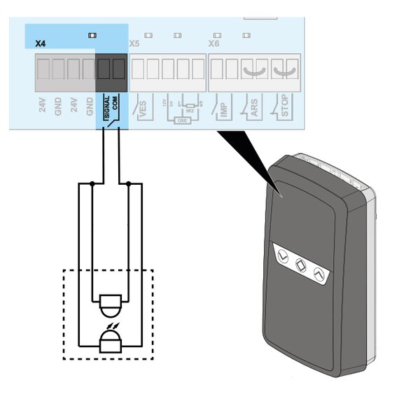
How is a 2-wire photocell connected to a SOMMER control? In our connection diagrams we show you how to connect the safety device correctly. Please select a product category to find the connection diagram for a 2-wire photocell of your product.
Connection diagrams for garage door operators
Connection diagrams for underground garage operators
Connection diagrams for swing gate operators
Connection diagrams for sliding gate operators
Connection diagrams for industrial door operators
Connection diagrams for roller door control units
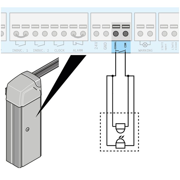
Connection diagrams for barriers
Connection diagrams for garage door operators
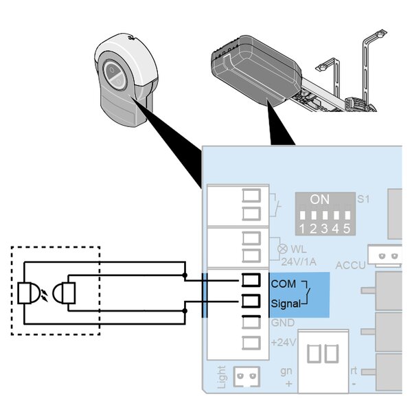
SOMMER base+ / SOMMER pro+
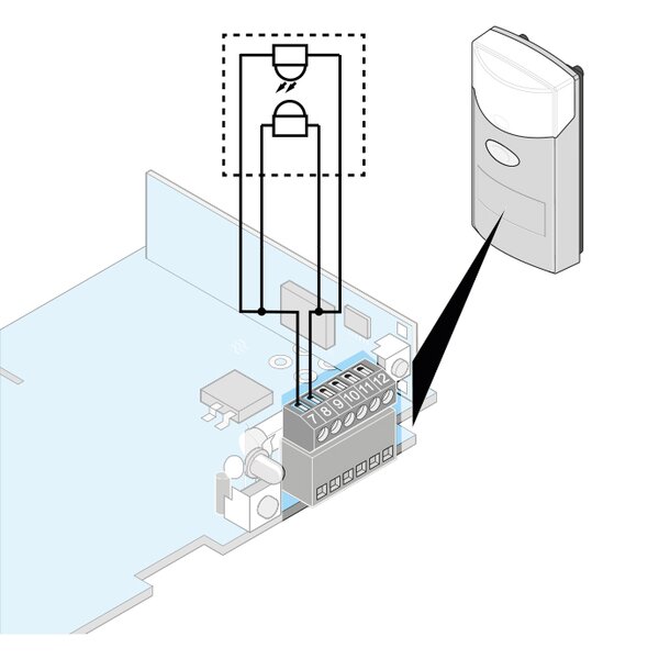
duo rapido+
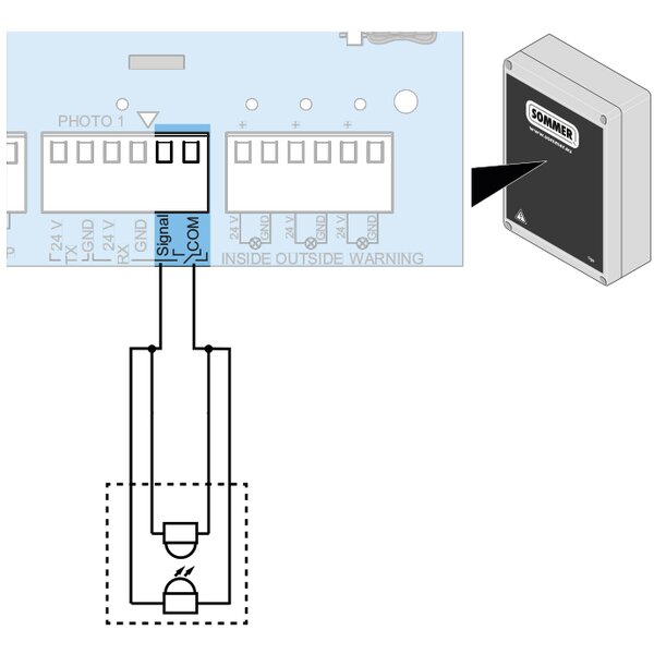
SOMMER tiga / tiga+
Connection diagrams for swing gate operators
To ensure correct functioning, light barriers and safety devices must be correctly installed, aligned and connected before initial commissioning. A 2-wire light barrier is included in the scope of delivery of the gate drive.
Additional light barriers can be purchased. The control unit has 2 connections for light barriers using 2-wire or 4-wire technology. Combinations are possible. It is recommended that the light barrier be installed at a height of up to 300 mm. For reasons of material protection, it may be necessary, for example, to install an additional light barrier inside and outside at a height of 600 mm. Light barriers can only be connected in series with light barriers using 4-wire technology. For the positions of the light barriers on the gate system, see the application example in chapter “3.1 The operator and how it works” of the assembly and operating instructions.
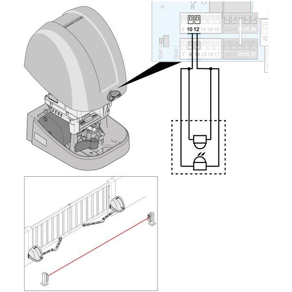
twist AM
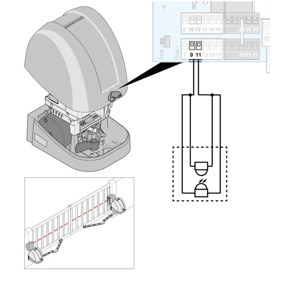
twist AM
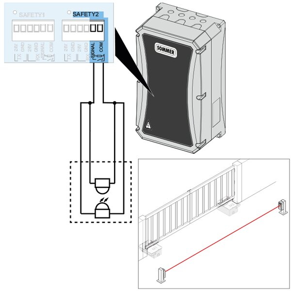
twist UG
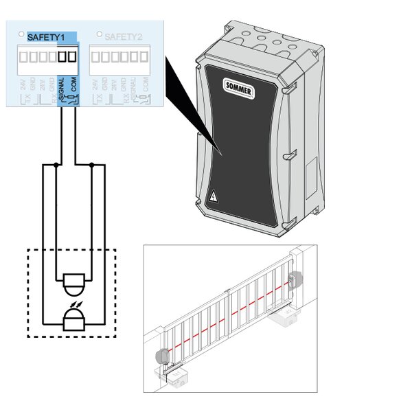
twist UG
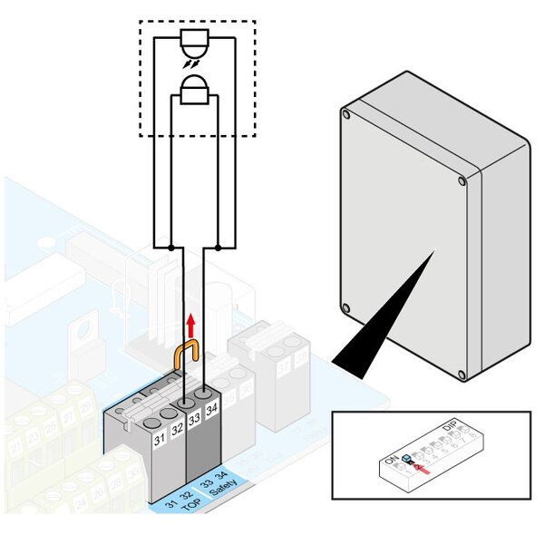
twist 350 / twist rapido 350 / twist XL
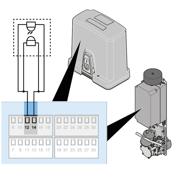
RUNner / RUNner+ / SP 900 / S900
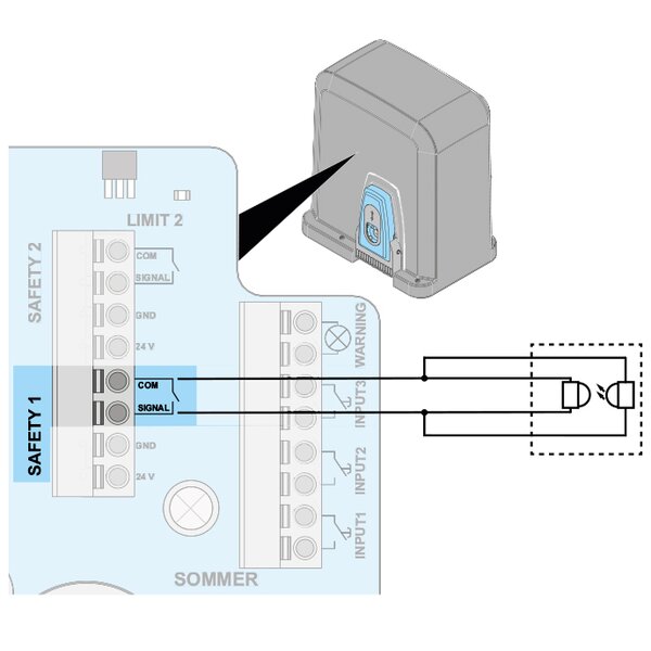
STArter S2 / STArter S2+
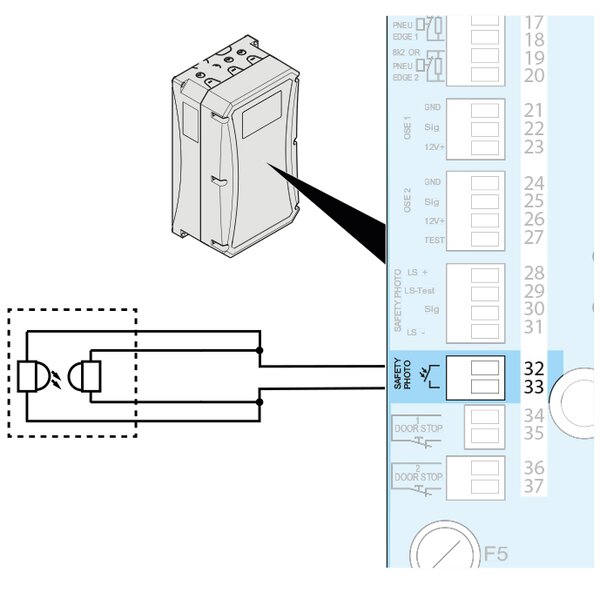
GIGAcontrol A

GIGAcontrol TA
RDC Vision+
