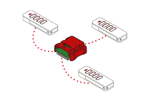
More comfort & safety through our radio system
Sliding gate operator STArter S2 / STArter S2+
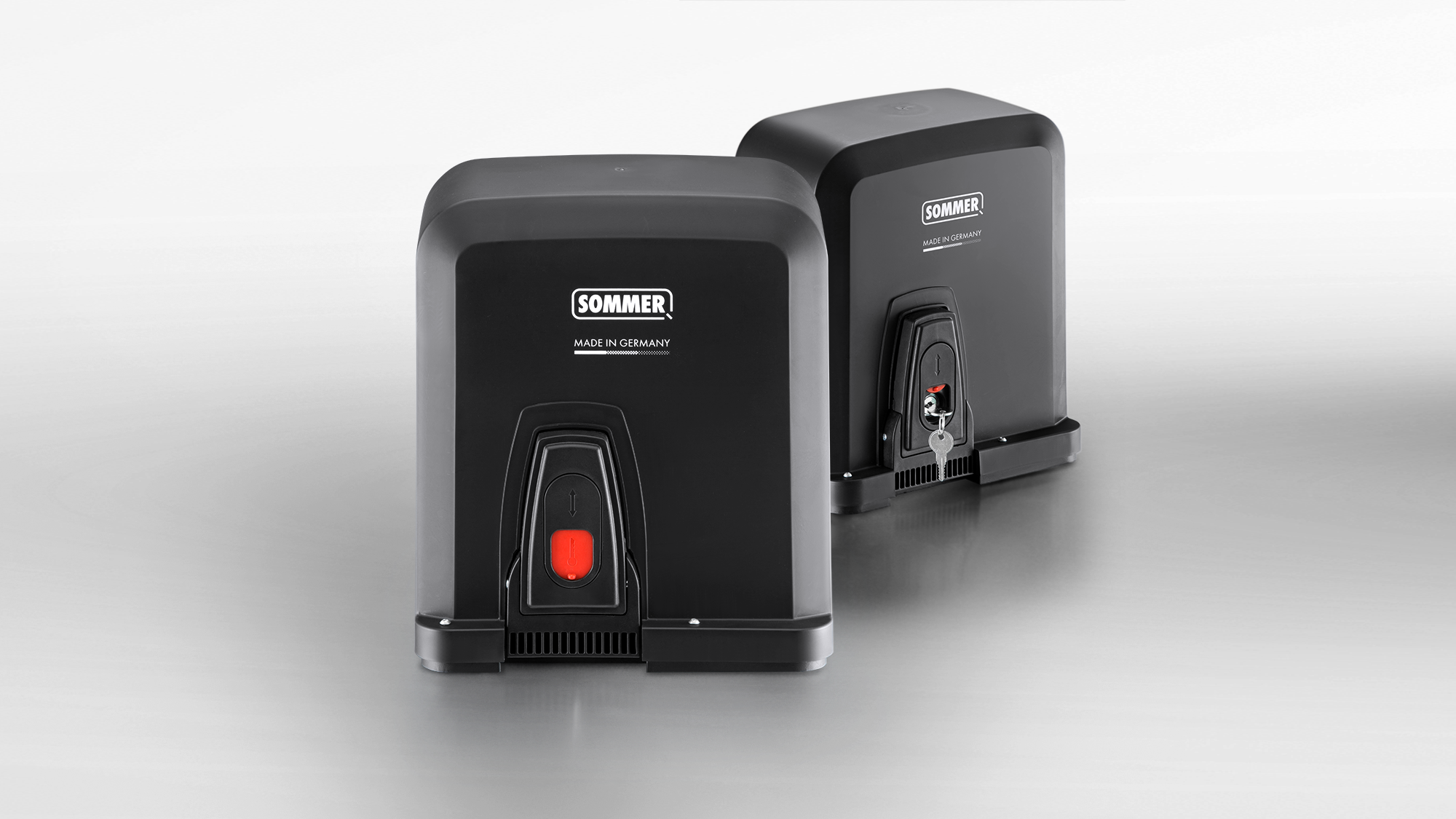
Intelligent sliding gate operators with impressive travel dynamics
The intelligent sliding gate operators in the STArter S2 range are the ideal operators for small to medium-sized sliding gates. Their intelligent control offers a wide range of connection options. In addition to convenient operation via radio control system, they can be integrated into the Smart Home systems SOMweb and Delta Dore. Sliding gate operator STArter S2+ provides an added advantage when it comes to gate weight, movement range and speed.
Product advantages
Accident prevention through electronically controlled force measurement
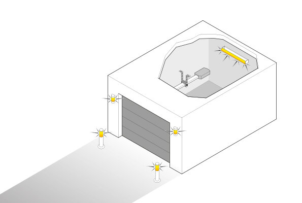
The operator learns on its own and runs in the currently most economical way thanks to the DPS (Dynamic Power System). It adapts to the environment and always moves at the same speed. For the operator, obstacles mean that it suddenly needs more force. In this case, it stops or reverses. This prevents injury and damage to property. SOMMER also offers additional safety accessories. (Photo eyes, safety contact strips, etc.)
Long lifetime thanks to gentle soft running
The gate and the operator are preserved thanks to the "Open" and "Close" soft running. Shortly before the gate end positions, the speed decreases, which preserves the mechanics and increases the lifetime. No annoying closing noises.
Power failure - what now?
The mechanical emergency release can be activated manually to open your gate when there is a power failure. Even if there is strong contact pressure on the operator, the release lock can be triggered with low application of force and you can get to your property.
Environmental and cost efficiency
Due to the economical toroidal transformer, power consumption and environmental pollution are low.
High quality and stable
The rugged plastic rack with integrated steel core ensures maximum stability.
Functions which make daily life easier
The partial opening function can be used to open a part of a gate and reach the property by bike, for example.
With the automatic closing function, you can be sure that the gate is always locked behind you. After the photo eye is passed, the gate automatically closes after a set time.

Additional equipment
With our additional equipment, you can generate your own optional added value. The modular system design enables you to expand the SOMMER door operator with numerous accessories according to the "plug and play" principle. All accessories can be easily assembled, as the slots are color-coded and labeled exactly.

Open-Collector
Output OC
Transfers the door status (open/closed) to Smart Home systems. Optionally, a further external lighting unit can be operated.
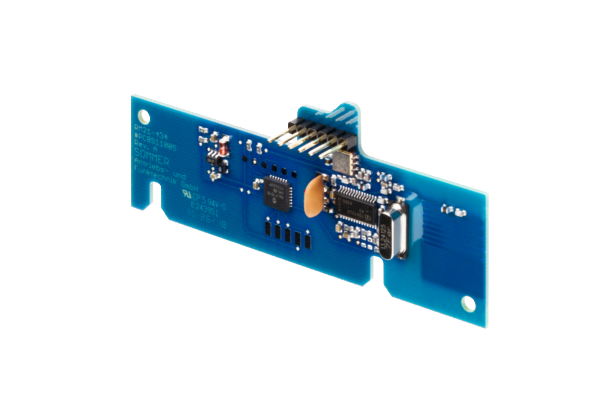
HomeLink radio receiver module
With the HomeLink radio receiver, the operator can be upgraded to the HomeLink radio control system. The operator can then be controlled with a HomeLink transmitter integrated in the vehicle.
Delta Dore X3D-Modul
The module Integrates the operator into the Delta Dore Smart Home system. This allows you to control and query the position of the operator via the Tydom app from Delta Dore.

Wall station
With the 3-command interior wall switch, you can open, stop and close the gate or use the holiday function for added security in your home.
Technical data
| STArter S2 | STArter S2 Set | STArter S2+ | STArter S2+ Set | |
|---|---|---|---|---|
| Max. gate weight | 300 kg | 300 kg | 400 kg | 400 kg |
| Max. travel | 6,000 mm | 6,000 mm | 8,000 mm | 8,000 mm |
| Max. gate inclination | 5 % | |||
| Max. opening speed | 190 mm/s | 190 mm/s | 240 mm/s | 240 mm/s |
| Max. torque | 11 Nm | 11 Nm | 11 Nm | 11 Nm |
| Power consumption (standby) | 3 W | 3 W | 3 W | 3 W |
| Nominal voltage range 1 | 220-240 V | 220-240 V | 220-240 V | 220-240 V |
| Rated frequency | 50-60 Hz | 50-60 Hz | 50-60 Hz | 50-60 Hz |
| Temperature min. | -20 °C | -20 °C | -20 °C | -20 °C |
| Temperature max. | 50 °C | 50 °C | 50 °C | 50 °C |
| Protection class | IP54 | IP54 | IP54 | IP54 |
| Radio system | SOMloq2 | SOMloq2 | SOMloq2 | SOMloq2 |
| Radio frequency | 868.95 MHz | 868.95 MHz | 868.95 MHz | 868.95 MHz |
| Radio memory locations | 40 | 40 | 40 | 40 |
No active safety contact strip on the main closing edge is necessary for the STArter S2. A passive rubber profile is sufficient.
Active safety contact strips must be used on the main and auxiliary closing edges with the STArter S2+.
FAQ
Frequently asked questions and answers
The installation and operating manual for the STArter S2 and STArter S2+ can be downloaded from the download portal.
The design data for the STArter S2 and STArter S2+ can be downloaded from the download portal.
With optional accessories, the intelligent sliding gate operators can be controlled from a smartphone, tablet or PC. In order to operate the STArter S2 or STArter S2+ via Smart Home, you need the SOMweb Smart Home solution or a Delta Dore X3D module.
If a SOMweb is installed, the sliding gate operator can be added in the app. With the Delta Dore X3D module, you can integrate the sliding gate operator into the existing Smart Home system from Delta Dore.
The operator only functions with a connected photocell.
With the optional HomeLink radio receiver module, the sliding gate operators STArter S2 and STArter S2+ are compatible with HomeLink.
The predecessor models STArter and STArter+ can be simply replaced with a STArter S2 or STArter S2+. The mounting points, the pinion and the pinion height are identical to the predecessor model. You will need to replace the handheld transmitters if they are not compatible with the SOMloq2 radio system.
- Is the mains power supply connected?
- Are the fuse and the main switch switched on?
- Have a specialist check the voltage supply at the operator.
- The emergency release was activated; unlock the sliding gate operator.
- The command device is not connected to the operator correctly; check the connection.
- The command device is defective
- The safety device has been activated, e.g. safety contact strip, photocell, emergency stop etc.
- Holiday mode was activated at the Wallstation; the command devices are locked.
- The transmitter is not programmed on the operator or is programmed to the wrong radio channel.
- The transmitter battery is flat or there is no mains power supply.
- The fuse or the main switch is not switched on.
- Have a specialist check the voltage supply at the operator.
- The emergency release was activated; unlock the sliding gate operator.
- The safety device has been activated, e.g.: safety contact strip, photocell, emergency stop etc.
- Holiday mode was activated at the Wallstation; the command devices are locked.
- The memory for transmitters is full. You can extend it with the Memo memory extension.
- The transmitter is not compatible with the Somloq2 radio system. Check the compatibility.
- The system code of the transmitter does not match that of the sliding gate operator. You can find the system code on the type plate of the transmitter and operator.
- The radio frequency does not match that of the sliding gate operator. You can find the radio frequency on the type plate of the transmitter and operator.
- Programming of a transmitter was locked by SOMlink. Ask your specialist dealer or installer.
- A Memo was created with the Codemaster+ transmitter management. Ask your specialist dealer or installer.
- The safety devices must be programmed when retrofitting. Press the Reset key for one second.
- Check the connection of the safety devices
- The safety device is defective
- The direction of action is reversed. Check the function and the connection. Ask your specialist dealer or installer.
- The selected installation position is incorrect. Check the DIP switch setting.
- The direction of action is reversed. Check the function and the connection. Ask your specialist dealer or installer.
- The selected installation position is incorrect. Check the DIP switch setting.
- The safety device is activated before movement or is defective. Check the safety devices.
- A motor return is detected from outside, for example due to attempted break-in.
- The photocell or safety device is activated
- Remove any obstacle present.
- Check the safety devices.
- Check the alignment of the photocell.
- The operating mode Defined opening/closing is selected
- The operating mode Automatic closing is selected. Wait for the hold open time (factory setting 60 seconds) to elapse.
- The obstacle detection has been triggered. Check the movement area and running characteristics of the gate.
- The photocell or safety contact strip has been interrupted during movement.
- The switching solenoid is not mounted on the rack
- The switching solenoid is not reaching one of the reed sensors. Consult the section End position setting in the manual for further details.
Specialist dealer
Find a retailer near you
Our specialist dealers provide the perfect and safe all-round service for full customer satisfaction.